

Some patents quietly shape the future of connectivity without much notice, until their technical designs become central to emerging technologies. US7724143B2 is one of those patents.
Recently cited in the matter of VTT Technical Research Centre of Finland Ltd. v. HID Global Corporation et al, this patent outlines a compact yet sophisticated antenna construction for RFID systems. Its core idea: a folded conductive structure that supports magnetic field generation and dual-terminal connectivity, has resonated across RFID-enabled hardware applications.
Rather than focusing on litigation specifics, this article utilizes the Global Patent Search (GPS) platform to identify a network of related patents with overlapping structural and conceptual designs. By analyzing these comparable patterns, we aim to understand how the technical contributions of US7724143B2 align with similar inventions.
If you’re in product design, wireless infrastructure, or simply interested in how RFID antennas evolve, this GPS-powered exploration offers a structured and insightful perspective.
Understanding Patent US7724143B2
US7724143B2 discloses an innovative antenna construction optimized for use in RFID transponder systems. The invention features a unique folded design where a conductive ground plane, transmission line, and insulation layer work in tandem to enable efficient magnetic field generation. The configuration minimizes the need for vias, simplifies manufacturing, and supports thin, surface-mountable applications.
Source: Google Patents
Its four key features are
#1. Folded edge magnetic source: A fold in the antenna structure acts as the primary source of the magnetic field.
#2. Double-terminal connectivity: An RFID component is connected via two terminals, one linked to the transmission line, the other to a second line or the fold.
#3. Thin, surface-compatible design: Built for flat surfaces, such as packaging, the structure supports compact deployment with long reading distances.
#4. No via requirement: Eliminates grounding vias, reducing cost and enabling roll-based, continuous manufacturing processes.
Technically, this patent addresses key challenges in RFID design, namely efficiency, compactness, and ease of integration, through a novel folded antenna architecture. Its influence extends across applications demanding durable, low-profile, and cost-effective wireless tagging solutions. See our stress test of US9251332B2, showcasing how physical tokens are central to modern secure access systems.
Similar Patents As US7724143B2
To explore the innovation landscape surrounding US7724143B2, we ran the patent through the Global Patent Search tool. Below is a quick glimpse of the GPS tool in working:

Source: Global Patent Search
This analysis surfaced a series of related patents showing parallel developments in antenna miniaturization, feed design, and impedance matching techniques for RFID systems. Highlighted below is one such reference that offers relevant insight into compact, efficient RFID antenna structures using inductive feeding and flexible manufacturing strategies.
#1. KR20060064454A
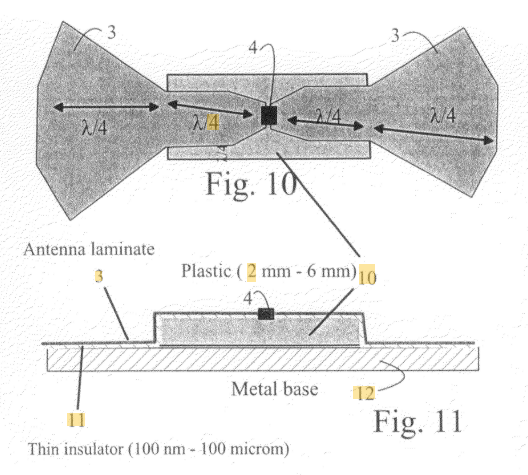
This Korean patent, KR20060064454A, published in June 2006, introduces a compact RFID antenna that uses inductively coupled feeding to improve impedance matching and operational efficiency. Featuring a meandered trapezoidal dipole structure, the design enhances effective length while maintaining broadband capabilities and manufacturing simplicity.
Source: GPS
What Does This Patent Introduce to the Landscape?
- Meandered dipole design – Extends antenna length without increasing physical dimensions, supporting broadband signal response in a small footprint.
- Inductive coupling feed – Employs a rectangular loop-based feeding unit to enable non-contact power delivery and impedance matching.
- Modular feed unit – Separates the power feed section for standardized production, simplifying the integration of RFID chips with antennas.
- Low-cost fabrication – Supports antenna patterning via etching, deposition, or printing with materials like copper, aluminum, or conductive ink.
How Does It Connect to US7724143B2?
While US7724143B2 generates magnetic fields through a structural fold to support RFID transmission, KR20060064454A achieves a similar goal using inductive coupling and geometric shaping. Both inventions pursue minimal, efficient antenna configurations that eliminate the need for vias. The shared themes include:
- Alternative feed strategies for compact antenna integration
- Thin, substrate-based construction suitable for mass production
- Enhanced performance despite small physical size
Why Does This Matter?
This reference illustrates a parallel design approach to addressing RFID antenna challenges, including size, efficiency, and cost. Just like US7724143B2, it shows how inventive feed architecture and smart material use can lead to scalable, high-performance tag solutions.
If you’re exploring how location-triggered systems evolved into personalized mobile services, our deep dive into US8559970B2 breaks down how user preferences and real-time positioning work together to deliver customized information.
#2. JP2006109396A
This Japanese patent, JP2006109396A, published in April 2006, introduces a wireless tag antenna system that employs an auxiliary diamond-shaped pattern to enhance bandwidth and support efficient impedance matching with IC chips. The design enhances tag readability, even in scenarios where the tag is affixed to paper-based materials, such as books.
Source: GPS
What Does This Patent Introduce to the Landscape?
- Auxiliary diamond-shaped pattern – Doubles the antenna surface area to achieve a wider frequency band and lower impedance.
- Targeted impedance matching – The geometry supports smoother electrical connection to IC chips, improving signal strength and system reliability.
- Optimized layout for tag placement – Addresses performance issues when tags are mounted on absorbent or irregular surfaces like paper.
- Directional reading enhancement – Improves antenna directivity, enabling consistent readability even without a specialized reader casing.
How Does It Connect to US7724143B2?
Both patents focus on enhancing RFID tag efficiency and read range by optimizing the physical antenna structure. While US7724143B2 utilizes a folded configuration to manipulate magnetic fields and minimize impedance issues, JP2006109396A takes a surface-patterned approach. Their shared goals include:
- Supporting compact RFID tag construction with high signal performance
- Enhancing impedance matching for better chip integration
- Improving readability across varying placement conditions
Why Does This Matter?
This reference highlights another strategy for optimizing RFID antennas through geometric enhancement and smart pattern design. Alongside US7724143B2, it reinforces the trend of tuning antenna structure to extend function, particularly in environments where mounting surfaces limit performance.
#3. KR20060064473A
This Korean patent, KR20060064473A, published in June 2006, presents a Planar Inverted-F Antenna (PIFA) designed for use in metal-adhered active RFID tags. It features a meander line along the non-radiating edge and a stub extension to control reactance, enhancing impedance matching and read reliability even in unstable electromagnetic environments.
Source: GPS
What Does This Patent Introduce to the Landscape?
- Meander line integration – Positioned on non-radiating edges to fine-tune resonance frequency and facilitate bandwidth adaptability.
- Stub for reactance control – Enables fine adjustment of antenna impedance for optimal RF performance in variable conditions.
- Short-circuit structure – Connects radiating patch to ground plane to support the PIFA configuration and increase communication stability.
- Metal-adhesive design – Tailored for active RFID systems where tags are placed on metallic surfaces prone to interference.
How Does It Connect to US7724143B2?
US7724143B2 eliminates vias by using a folded antenna to manage magnetic field generation and impedance. Similarly, KR20060064473A reconfigures edge structures and feed lines to stabilize impedance under difficult environmental conditions. Both pursue:
- Efficient antenna performance on non-ideal surfaces
- High adaptability to real-world mounting scenarios
- Structural innovations to reduce the impact of electromagnetic instability
Why Does This Matter?
This reference demonstrates a material-specific approach to enhancing RFID tag communication, particularly for applications involving high metal content. Together with US7724143B2, it demonstrates how tailored antenna geometries and reactive control elements can significantly boost system reliability and production flexibility.
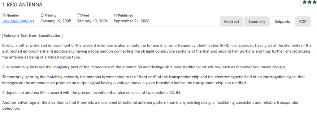
#4. US20060208900A1
This U.S. patent application, US20060208900A1, published in September 2006, introduces a folded dipole-type antenna for RFID transponders. Its design features straight conductive sections linked by a loop, increasing the imaginary component of impedance and enabling more omnidirectional radiation, improving detection reliability across various reader positions.
Source: GPS
What Does This Patent Introduce to the Landscape?
- Folded dipole configuration – Uses a loop to connect two conductive arms, enhancing current distribution and antenna responsiveness.
- Impedance optimization – Increases the imaginary impedance to facilitate better chip rectification during signal reception.
- Direct transponder connection – Bypasses intermediate matching networks by linking the antenna directly to the transponder’s front end.
- Omnidirectional performance – Delivers a more uniform radiation pattern than meander-line designs, improving tag readability from multiple angles.
How Does It Connect to US7724143B2?
Both patents aim to maximize RFID tag efficiency by manipulating antenna geometry. While US7724143B2 achieves performance gains through folded structural design and surface integration, US20060208900A1 enhances impedance and signal capture using a folded dipole approach. Key overlaps include:
- Fold-based architecture to improve signal behavior
- Structural tuning for impedance matching without additional components
- A focus on passive RFID systems requiring minimal circuitry
Recommended read: US11395509B1 demonstrates how folded structural design and modular inserts are being applied in consumer smoking accessories for enhanced functionality.
Why Does This Matter?
This reference reinforces the utility of folded configurations in RFID antenna design. Alongside US7724143B2, it highlights the recurring need to fine-tune impedance and signal response through geometric innovation, enabling simple, effective solutions for power- and cost-sensitive RFID applications.
If you’re exploring controlled material-surface interactions, EP4249647A1 offers a unique approach using solid electrolyte particles suspended in a non-conductive fluid for precision metal polishing.
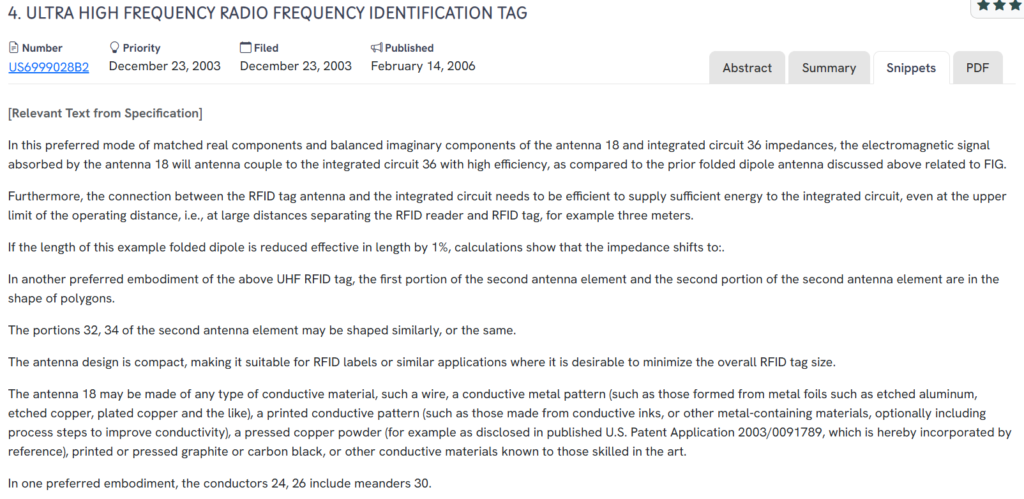
#5. US6999028B2
This U.S. patent, US6999028B2, published in February 2006, details a compact UHF RFID tag featuring a folded dipole antenna optimized for efficient energy transfer to an integrated circuit. By matching real components and balancing imaginary impedance, the design ensures reliable signal capture and power delivery, especially at longer read distances.
Source: GPS
What Does This Patent Introduce to the Landscape?
- Impedance-balanced folded dipole – Aligns antenna and chip impedances to maximize power coupling and signal absorption.
- Polygon-shaped elements – Uses polygonal conductor patterns to fine-tune the antenna structure while maintaining compactness.
- Extended read range – Efficient energy transfer supports strong tag performance even up to three meters away from the RFID reader.
- Flexible material compatibility – Supports various conductive materials, including etched metal foils, printed inks, or pressed conductive powders.
How Does It Connect to US7724143B2?
Similar to US7724143B2, this patent aims to enhance RFID tag performance by addressing physical and electrical design challenges. While US7724143B2 employs folded conductive paths and layered surfaces, US6999028B2 optimizes antenna-to-chip coupling and compact form factor using folded dipole geometry. Shared innovations include:
- Structural design tailored for impedance matching
- Compact configurations for label-based RFID solutions
- Focus on passive UHF operation with long read range
Why Does This Matter?
This reference highlights the importance of impedance matching in enhancing system reliability and extending the distance. Together with US7724143B2, it emphasizes the ongoing need for thoughtful antenna engineering to meet real-world deployment requirements without increasing cost or complexity.
How to Find Related Patents Using Global Patent Search?

Understanding how a patented design fits within a broader network of innovations can be critical for technical evaluation, product development, or identifying engineering trends. The Global Patent Search tool is built to simplify that task, especially for antenna technologies like those in US7724143B2. Here’s how it works:
1. Enter the patent number into the GPS: Input the patent number, such as US7724143B2, into the GPS tool. The platform instantly generates a refined search based on antenna construction, impedance design, and radio-frequency system attributes.

2. Explore conceptual snippets: Instead of mapping specific claim elements, GPS now uses intelligent text snippets that reveal overlaps in structural features, signal behavior, and manufacturing methods.
3. Identify related inventions: The tool highlights patents with similar architectural goals, such as folded dipole designs, non-via impedance matching, and compact form factors for RFID systems.
4. Compare concepts without legal framing: GPS emphasizes system-level operation and technical relevance, avoiding the need to parse through legal claims or litigation details.
5. Accelerate cross-domain discovery: Whether you’re researching RFID systems, embedded antenna solutions, or wireless tag manufacturing, GPS provides clear, context-based insights to navigate this space.
With these capabilities, Global Patent Search enables hardware developers, patent analysts, and R&D teams to uncover related ideas, streamline product strategies, and stay ahead of emerging innovations in wireless identification technologies. Start your next discovery with Global Patent Search.
Disclaimer: The information provided in this article is for informational purposes only and should not be considered legal advice. The related patent references mentioned are preliminary results from the Global Patent Search tool and do not guarantee legal significance. For a comprehensive related patent analysis, we recommend conducting a detailed search using GPS or consulting a patent attorney.