
Think about how often projectors are moved today. From meeting rooms to classrooms to home setups. They’re unplugged, packed, mounted, and adjusted repeatedly. Unlike fixed electronics, projectors are routinely repositioned after deployment, and every move introduces mechanical stress inside the device.
Now, inside these projectors sits a very sensitive part called a digital micromirror device. It has to stay perfectly connected to the main board. If not, the assembly failed or image quality suffered. For the longest time, that connection was rigid, adding to the woes.
That’s where US8562149B2 comes in. The patent focuses on making the connection flexible instead of forcing everything to stay stiff. That way, projectors can become easier to assemble.
The design choices were key to making projectors reliable over time and is now central to a dispute between iMod Systems LLC and Hisense Co., Ltd.
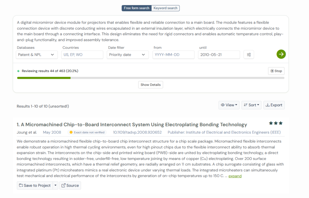
To understand how this approach developed, we used the Global Patent Search tool to examine earlier hardware designs and their evolution. But first, let’s understand the patent a bit more.
Understanding the Patent US8561249B2: Why Flexibility Matters Inside a Projector
To understand US8562149B2, it helps to picture what’s happening inside a projector while it’s running.
Light is bouncing, mirrors are flipping thousands of times a second, heat is building up, and in the middle of all this, the digital micromirror device has to stay perfectly connected to the main board.
Earlier designs treated this connection like a fixed handshake. Two rigid boards. One exact position. There was no room for error. If things lined up, great.
If not, you would face trouble during assembly, signal issues later, or limits on how small the projector could be.
This patent steps back and asks a calmer question: what if the connection didn’t need to be stiff at all?
Instead of locking the micromirror device onto a rigid board, the patent places it on a flexible connection. The wires are sealed, protected, and carefully arranged, but they can bend. That flexibility gives manufacturers breathing room. Parts can be positioned more freely. Assemblers can see what they’re doing. Heat can be managed without forcing everything into one tight stack.
Key Features of US8562149B2:
At its core, this patent focuses on making the connection between key projector components easier to assemble, install, and maintain. Here are the key features:
- Flexible connection instead of rigid boards: The digital micromirror device is connected using a flexible cable rather than stiff board-to-board connectors. This allows the module to bend slightly instead of forcing perfect alignment.
- Side-mounted connection for better assembly: The connecting interface sits on the side, not underneath. This makes it easier for technicians to see and confirm that everything is connected properly during assembly.
- Supports smaller and cleaner internal layouts: Because the connection is flexible, the DMD module can be placed where it fits best. This helps reduce internal clutter and supports smaller projector designs.
- Built-in heat handling support: The design allows for heat sinks and even automatic cooling fans to be added directly to the module, helping protect the micromirror device over time.
Taken together, these features don’t change how a projector looks or works from the outside.
They quietly make it more reliable, easier to assemble, and better suited for compact modern designs.
A similar reliability problem shows up inside chip packages as well, where US8258611B2 addresses a fix for internal delamination that can quietly weaken electrical connections over time.
4 Earlier Patents That Shaped Flexible Projector Design
Long before flexible DMD connections became practical, engineers were already experimenting with better ways to connect, cool, and protect sensitive components inside compact electronic devices.
To trace how these ideas developed over time, we used the Global Patent Search tool. Instead of relying on keyword-based searches, GPS surfaces earlier inventions tackling similar connection and layout problems.
Let’s explore some of them.
1. JP3470958B2: Designing for Imperfection, Not Precision
Imagine an engineer on a production floor, watching boards come off the line. On paper, everything is supposed to fit neatly. Pads are aligned, connectors are precise, and the design looks flawless. But once assembly starts, reality steps in.
Some boards pass testing without issues. A few work initially and then fail after a short period of use. Nothing obvious is broken, and yet the pattern keeps repeating. After enough inspections, the root cause becomes clear. The problem is not bad components. It is tiny misalignment.
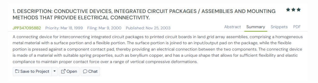
JP3470958B2 was filed in 2000, when engineers started accepting this reality instead of fighting it. The patent does not try to force tighter tolerances or stricter assembly. Instead, it introduces connectors that can flex slightly when pressure is applied. Each contact adjusts itself just enough to maintain proper electrical contact, even when the surfaces are not perfectly flat.
This changes how reliability is achieved. Instead of relying on perfect alignment, the system relies on adaptability. Manufacturing variation stops being a risk factor because the connector absorbs it quietly.
This mindset shaped the subject patent. Once engineers accept that connections can move a little without failing, it becomes possible to separate sensitive components from rigid boards using flexible links.
2. US5248262A: Packing More Connections Without Making Them Fragile
By the early 1990s, computer systems were struggling to connect more things in less space.
As processors, boards, and modules became denser, connectors had to carry more signals while staying reliable, removable, and tolerant of dust, wear, and repeated use. Rigid pins and soldered joints started to show their limits. High density made everything less forgiving.
US5248262A, filed by IBM in 1992, tackled this pressure head-on. Instead of relying on stiff contacts or permanent joints, the patent introduces flexible circuit members inside a connector housing. These members bend when compressed, press firmly against pads, and even create a wiping action that clears debris during contact.
This patent changed how high-density systems behave. Connections stopped acting like delicate glass and start behaving like working parts. Boards could be connected, tested, removed, and reconnected without damaging the interface.
That thinking carries directly into the subject patent US8562149B2. Once connectors are allowed to flex without failing, sensitive modules no longer need to sit perfectly aligned on rigid boards. Flexible links become safe, predictable, and repeatable. The subject patent builds on this same lesson, using flexibility to handle dense layouts without turning reliability into a gamble.
What’s interesting is how this thinking repeats across domains. In temperature control systems, US7249882B2 tackles the same core issue by using system behavior, not fixed assumptions, to guide PID tuning.
3. US6086386A: Making Chip Connections Flexible Without Making Them Tall
As chips became more powerful in the late 1990s, another quiet problem started showing up.
They needed more connections, but there was no room to grow upward.
Traditional sockets and connectors added height. Flexible wires helped with compliance, but they were hard to control and didn’t scale well as I/O counts exploded. Engineers were stuck choosing between flexibility and a slim profile.
US6086386A, filed in the late 1990s by Tessera Inc, takes a different route. Instead of using bulky sockets or loose wires, it introduced the idea of a thin, sheet-like connector where flexible regions sit exactly where the chip’s bump leads land. Each contact is surrounded by material that can bend locally, not globally.
Only the areas that need to move actually move. The rest stays stable and low-profile. Chips can press down, connections flex just enough to absorb stress, and everything stays compact.
Once movement is confined like this, flexible connections stop fighting enclosure limits. They start fitting naturally into tight layouts, instead of forcing designers to redesign everything around them.
That idea quietly clears the path for flexible internal links to exist inside compact systems, without changing how those systems look or feel from the outside.
4. US5624268A: Connecting Tiny Contacts Without Solder or Heat
For a long time, making an electrical connection meant committing to it.
Once solder flowed, the decision was final. Heat was applied, parts were fixed in place, and undoing a mistake usually meant damage. That approach worked when connections were large and forgiving. It struggled when contact points became microscopic.
US5624268A, filed by The Whitaker Corporation, steps away from permanence altogether. Instead of bonding metal to metal, it introduces a thin film that connects only when pressure is applied.
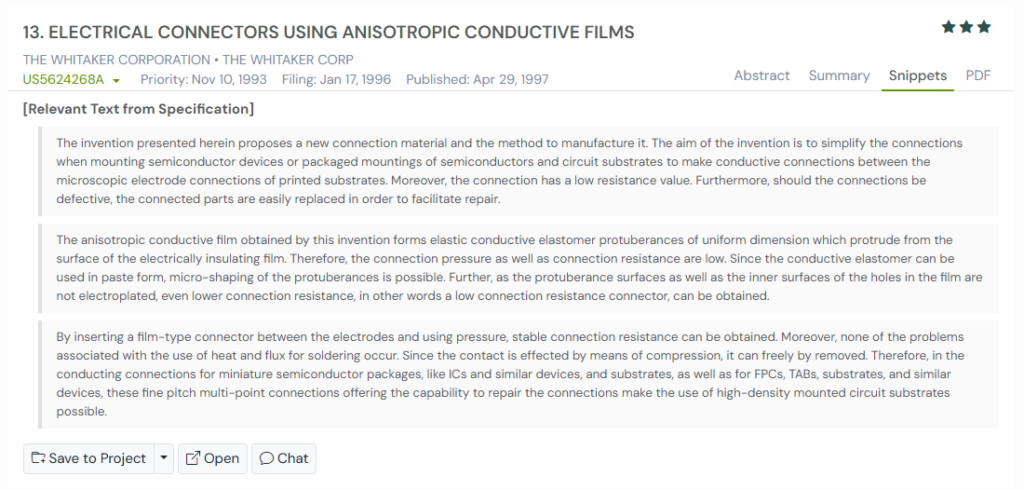
Inside that film are tiny elastic conductive bumps. Press two surfaces together and electricity flows straight through. Release the pressure, and the connection disappears.
That meant connections could be tested, adjusted, removed, and rebuilt without damage.
And that mindset is foundational for patents like US8562149B2 which allows flexible internal connections to exist comfortably inside modern devices. Not everything needs to be fixed forever. Some connections just need to work when they’re needed, and move on when they’re not.
Many security failures stem from the fact that digital identifiers can be copied. US7493497B1 addressed this weakness by anchoring identity directly into the microprocessor, creating a form of trust that cannot be duplicated in software.
How Earlier Patents Approached the Same Connection Problem
Each of these patents attacks the same core challenge from a slightly different angle. Instead of perfect alignment or permanent bonding, they explore flexibility, compliance, and repairability as ways to improve reliability.
Looking at them side by side makes it easier to see how thinking around electrical interconnects gradually evolved.
Here’s a simplified comparison of the five earlier patents and what each one contributed.
| Patent | Year (Priority) | Core Problem Addressed | Key Idea Introduced | Why It Mattered |
| JPP3470958B2 | 1999 | Misalignment between pads and boards | Flexible, spring-like connectors that bend under pressure | Absorbed manufacturing variation instead of fighting it |
| US5248262A | 1992 | High-density connections becoming fragile | Flexible circuit members with wiping action | Made dense connectors reliable, removable, and debris-tolerant |
| US6086386A | 1996 | Rising I/O counts with strict height limits | Localized flexibility in thin, sheet-like connectors | Delivered compliance without increasing package height |
| US5624268A | 1993 | Heat and irreversibility of solder at small scales | Anisotropic conductive films using pressure-only contact | Enabled solderless, repairable, fine-pitch connections |
Using Global Patent Search to Trace Patents That Made Connections Reliable
When you step back and look at these patents together, one thing becomes clear. The real value isn’t in any single invention. It’s in the patterns that repeat across decades.
That’s where Global Patent Search becomes useful.
Instead of reading heavy jargon laded patents one by one, GPS helps you move sideways through innovation. You start with a subject patent, then explore earlier patents that solved similar problems in different ways.

Here’s how we used it for this analysis:
- Enter the subject patent into GPS to anchor the search.
- Use the sort by relevance option to bring the most closely related inventions to the top.
- Scan summaries and snippets to spot recurring ideas like flexibility, controlled pressure, or solderless contact.
- Dive deeper into full documents only when a concept shows meaningful overlap or differentiation.
This approach saves time and makes relationships between inventions easier to see.
If you want to understand how a technology evolved or spot prior art before building something new, GPS helps you do that faster and with more clarity.
Try the Global Patent Search tool today and explore innovation as a connected story, not a stack of documents.
Frequently Asked Questions
1. Why do modern electronic devices use flexible connectors instead of rigid ones?
Flexible connectors absorb small alignment errors, vibration, and thermal expansion that rigid connectors struggle with. As devices become smaller and more complex, even tiny mismatches can cause failures. This flexibility allows connections to maintain stable electrical contact without stressing components, improving reliability and lifespan in compact electronics.
2. What problems do rigid electrical connections cause in high-density electronics?
Rigid connections demand near-perfect alignment. In high-density designs, this leads to uneven pressure, cracked solder joints, signal loss, or intermittent failures. Heat, vibration, and repeated use makes these issues worse. Flexible interconnects reduces stress by allowing controlled movement instead of forcing parts to stay perfectly fixed.
3. How does controlled compliance improve connection reliability?
Controlled compliance means connections can move, but only within a designed range. This prevents excessive force from transferring into solder joints or pads while still maintaining firm contact. The result is better signal stability, fewer mechanical failures, and connectors that survive repeated insertion, removal, and temperature changes.
4. Why are solderless connections useful in small or delicate electronics?
Solderless connections avoid heat, flux residue, and permanent bonding. This makes them ideal for fine-pitch components, testing setups, and rework scenarios. They also allow parts to be connected, tested, removed, and reconnected without damage, which is especially valuable when dealing with tiny contacts or expensive components.
5. How do flexible interconnects help reduce device size?
Traditional connectors add height and bulk. Flexible interconnects spread compliance sideways instead of vertically. Only the contact areas move, while the rest stays thin and stable. This allows designers to pack more connections into less space, enabling slimmer devices without sacrificing electrical reliability or performance.
Disclaimer: The information provided in this article is for informational purposes only and should not be considered legal advice. The related patent references mentioned are preliminary results from the Global Patent Search tool and do not guarantee legal significance. For a comprehensive related patent analysis, we recommend conducting a detailed search using GPS or consulting a patent attorney.